I've been making some good progress with the robot, EAP, so I thought an update was in order.
I've got the eyes and eyebrow servos all mounted, with a battery pack powering them, and the RC receiver. I've also got the back cover of the reel-to-reel re-attached, which was a bit harder than I expected, since the servos were deep enough that the stuck out too far. I had to drill, cut, and file holes in the back cover for the servos to stick out. That's done though, and the original battery compartment cover still works, and I can access the new battery back through there. I filmed a little video playing around with controlling the eyes and eyebrows, trying out various expressions:
I think it's quite expressive, but I'm sure it will be even more so once we come up with some better eyebrows, and get the mouth working and attached as well.
In related news, Jeremy Lutter has posted a new video about the film (Joanna Makes a Friend) related to the robot construction:
A few weeks ago, I was contacted through a friend about helping out with building a robot for an indie short film. Since then, I've met with the other robot builder and the producer, and I've started work on the animatronic control for the robot head. The robot is named EAP, and he's going to be part of the short film Joanna Makes a Friend.
Yesterday, I picked up a 4 channel RC Airplane control and receiver, which I'll be using to control the animatronics. I temporarily mounted a couple servos with some speaker wire as eyebrows, to see how it looks when it's animated:
I'm pretty happy with how that worked out.
The eyes need to rotate both directions as well. Right now, they have motors attached:
(It's hard to concentrate on aiming the camera while trying to hold two wires in the other hand, and touch them to the diode chain. Also, since the camera was aimed straight down, the rotation sensor ended up deciding the video should be upside down.)
Unfortunately, those motors aren't controllable directly from the RC receiver. The motors rotate in one direction when positive voltage is applied, and at different speeds depending on the voltage, and rotate the other direction with negative voltage. Continous rotation servos, however, use PWM to indicate a rotational speed, and direction, but the voltage is always positive. Those can be controlled directly from the RC receiver:
I have a couple options for the eyes at this point:
Use the motors, and an Arduino to read the PWM from the RC receiver, and output a positive or negative voltage to run the motor. This has the advantage of being able to spin the motors quite quickly, and not needing to do any cutting or modifying to the mechanical bits of the reel-to-reel machine.
Remove the motors, and mount the eyes on continuous rotation servos. This has the advantage of being controlled directly from the RC receiver, so no fancy Arduino wiring needed to handle reverse voltage. However, it does mean cutting up the reel-to-reel machine to mount the servos.
Where I work, at Elastic Path, we have a CI build for our Java software that has some visible and audible feedback for the development team. We have a Ikea globe light that glows green or red if our build is passing or failing respectively, and an animatronic Yoda mask who's eyes glow the same colour. Yoda's mouth moves and he speaks a few Star Wars phrases whenever the build changes from red to green, or vice versa.
I found a little something in an antique store in Vernon recently that I decided I wanted to add to the build light.
Requirements:
Turn on for 10 seconds when the build goes from green to red.
Turn on for 10 seconds every 15 minutes until the build goes back to green.
The duration of the light should be adjustable via a knob, from 2 seconds to 30 seconds.
The delay for light going off should be adjustable via a knob, from 2 minutes to 30 minutes.
The "reminder" feature (going off every 15 minutes) should be able to be disabled via a switch.
There should be a button, that when pressed (regardless of the state of the build) will activate the light for the duration the button is pressed.
After playing around with some 555/556 timers, potentiometers, and various glue logic, trying to implement the first 4 requirements, I decided to just build an Arduino shield, and do it the easy way. I'm etching a PCB for the Arduino shield though, which I've never done before, so it's all a bit of an experiment and learning experience.
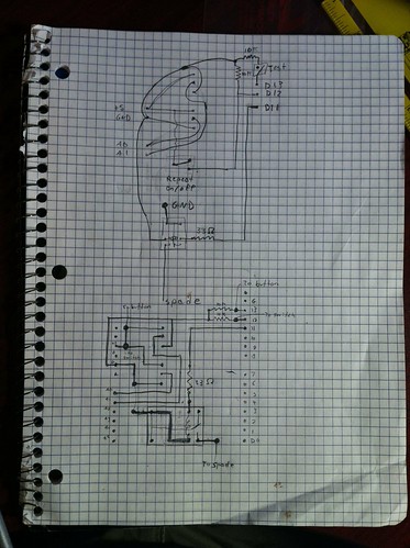
On Sunday, I finished prototyping the solution on an Arduino protoshield, and drew up a circuit diagram, trying to keep from having too many overlaps, then re-drew it with the actual layout of pins in mind a bit more:
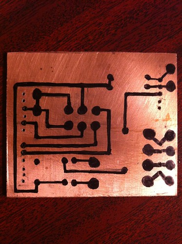
After that, I measured the headers on the Ardiuno board and used a pencil to draw them on to the PCB, and drilled holes for the pins I need to connect, plus a few I don't need, for "expansion" and to help secure the board to the Ardiuno nice and solidly. Then I started drawing the circuit layout, in pencil, making liberal use of the eraser, as I goofed up a few times. I original had one overlap in the circuit, which I planned to do with a jumper wire, but while drawing it in pencil, I managed to dream up a way to get rid of it. I also rearranged a bit of the circuit when I found I didn't have as much room in the center of the board as I thought, for the 6 pins for the 2 potentiometers. After getting it drawn in pencil, I went over it with a sharpie:
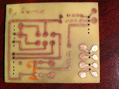
After about 23 minutes in ferric chloride etching solution, gently shaking it by hand the whole time, it was done. Cleaning the sharpie off with some isopropyl alcohol, and it's ready to be drilled, and everything soldered on:
Next is to finish drilling, and solder on all the bits and pieces.
On another note, can anyone find the mistake I made? I missed one critical bit of the circuit when I did the sharpie.