Where I work, at Elastic Path, we have a CI build for our Java software that has some visible and audible feedback for the development team. We have a Ikea globe light that glows green or red if our build is passing or failing respectively, and an animatronic Yoda mask who's eyes glow the same colour. Yoda's mouth moves and he speaks a few Star Wars phrases whenever the build changes from red to green, or vice versa.
I found a little something in an antique store in Vernon recently that I decided I wanted to add to the build light.
Requirements:
- Turn on for 10 seconds when the build goes from green to red.
- Turn on for 10 seconds every 15 minutes until the build goes back to green.
- The duration of the light should be adjustable via a knob, from 2 seconds to 30 seconds.
- The delay for light going off should be adjustable via a knob, from 2 minutes to 30 minutes.
- The "reminder" feature (going off every 15 minutes) should be able to be disabled via a switch.
- There should be a button, that when pressed (regardless of the state of the build) will activate the light for the duration the button is pressed.
After playing around with some 555/556 timers, potentiometers, and various glue logic, trying to implement the first 4 requirements, I decided to just build an Arduino shield, and do it the easy way. I'm etching a PCB for the Arduino shield though, which I've never done before, so it's all a bit of an experiment and learning experience.
On Sunday, I finished prototyping the solution on an Arduino protoshield, and drew up a circuit diagram, trying to keep from having too many overlaps, then re-drew it with the actual layout of pins in mind a bit more:
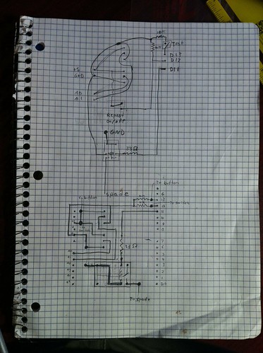
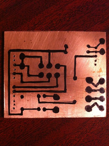
After that, I measured the headers on the Ardiuno board and used a pencil to draw them on to the PCB, and drilled holes for the pins I need to connect, plus a few I don't need, for "expansion" and to help secure the board to the Ardiuno nice and solidly. Then I started drawing the circuit layout, in pencil, making liberal use of the eraser, as I goofed up a few times. I original had one overlap in the circuit, which I planned to do with a jumper wire, but while drawing it in pencil, I managed to dream up a way to get rid of it. I also rearranged a bit of the circuit when I found I didn't have as much room in the center of the board as I thought, for the 6 pins for the 2 potentiometers. After getting it drawn in pencil, I went over it with a sharpie:
After about 23 minutes in ferric chloride etching solution, gently shaking it by hand the whole time, it was done. Cleaning the sharpie off with some isopropyl alcohol, and it's ready to be drilled, and everything soldered on:
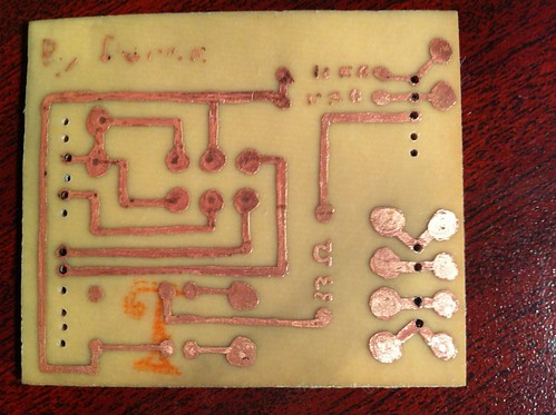
Next is to finish drilling, and solder on all the bits and pieces.
On another note, can anyone find the mistake I made? I missed one critical bit of the circuit when I did the sharpie.
1 comment:
I can only aspire to write material like this. I am extremely impressed with your presentation of the sound points in this article. Thank you for writing this engaging content.
ikea globe light
Post a Comment